This is an article about the Arduino controller boards and this opening piece gives an introduction to the Arduino and how it is used. It is not aimed at beginners in electronics, but more for giving information to those who have at least a reasonable knowledge of electronics components and circuitry and who would like to use the boards as an extension of their electronics work. Many of the current websites and printed publications about Arduino give a ‘form filling’ type of instruction whereby they just tell you to type this, connect this, etc. without any real in-depth background as to why you do these things or what happens behind the scenes when you do them. Those instructions may be suitable for beginners in electronics or indeed technology, but a seasoned technician would soon see there is much information lacking that they would wish to know.
Later articles will look at the interfacing of the boards to electronic circuitry and how to program the board to be able to control that environment. Also we will look at some interesting projects that will be useful.
What is an Arduino for?
An Arduino board is a single circuit board that is used for building and controlling electronics projects. You can connect to different electronic components and program the board to read the output of certain devices or to tell components what to do. The two classes of devices you can connect are input devices and output devices.
Examples of input devices: Switches; keyboards; environment sensors; cameras
Examples of output devices: LEDs; motors; solenoids; displays
The Arduino board can read the input from input devices. It can control what the output devices do. It can also control the output devices depending upon what the input device readings are. An example would be an infra-red sensor (input component) that detects body heat and a program that says that when the sensor has been activated that an output device (a warning lamp) should switch on. That is of course a very simple function that can be easily done without a controller board, but we have to start somewhere before moving on to more useful projects.
In the end, we want to create complex projects that a programmable board can undertake. We don’t want to end up with a simple Arduino-powered digital alarm clock because we can go to the store and buy a clock for pennies, but we will start off simple in order to get the basics undertaken before getting more ambitious.
The Arduino board and it’s interfacing with electronics and its programming can be a useful resource for learning about single board controllers but it can also be used as an end product to sense and control real-world objectives. The board itself and its software are open-source so that the internal makings of both can be fully analyzed, modified and shared.
The basic way in which you set up and use the Arduino board is to connect it to a computer, such as a Windows PC or a Linux computer or a MAC and create a program on that computer, which you then transfer to the Arduino and the board can then be disconnected from the computer and run that program on its own. When powered up without a computer connected, it will run whatever the last program was that was uploaded to it. The board is designed to run a program that has been uploaded to it rather than as an extension to a running PC, though there are some options to do that.
You don’t store different programs inside the board and then run each one when you want, like a PC is designed to do, so if you want separate functions to be performed then you would write separate sections within a single program.
Arduino vs Raspberry Pi
One of the most commonly known single board systems is the Raspberry Pi. Many people think the two devices are similar and you can choose one or the other for most tasks. While there are similarities between the two, they each have their more specific purposes.
A Raspberry Pi is a complete single board computer that can run on its own as a stand-alone device in a similar way that a Windows or Linux computer can run. It even uses a variation of the Linux operating system. It can store and run one or more of several applications and uses a CPU as its central core device.
An Arduino board has a microcontroller chip as its central core device. It is designed to run one program at a time and therefore usually used as a single function operating device.
Remember back a few paragraphs we said an Arduino can be programmed from a Linux computer, well you can connect a Raspberry Pi to an Arduino and program it from there. It might not be as elegant or efficient as a higher order PC, but it is supposed to work.
The similar characteristics of both boards are that they can both be used to program electronic projects as they each have programmable input and output interfaces. If you want to store and program several things then a Pi would be a preferable device, but for simpler and more straight-forward interfacing use an Arduino.
Different Arduino models
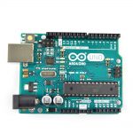
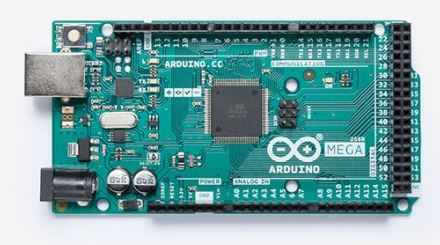
There are several different Arduino board types and each is suited to different scenarios, but by far the most common one is the UNO board, which is the one you normally read about and that most tutorials are based on. Here we will look at the UNO board first, but I will also be working with the MEGA board later, which is basically a UNO with an expanded number of inputs and output options and the extra memory and controls to use them.
Here are the two models:


Basic operations
Finally in this section is a quick overview of how you would set up and operate an Arduino board.
There are variations on how you can connect and program a board, but by far the easiest way and the method I will be using for these articles is to simply connect the board to a Windows PC using a USB cable. The USB cable supplies the power to run the board as well as providing a data interface to transfer the program from the PC.
The programming is done by installing a Java-based program called Arduino IDE (Integrated Development Environment) onto the Windows computer (there is also a Linux version). It comprises of an editor to write the ‘C’-like program (called a sketch) and a converter that transfers the program on to the Arduino by way of a loader program on the board. When we come to the software section later, I will expand upon the operations of IDE greatly.
I hope you found this section informative and are looking forward to the next article, which will look in detail at the hardware of the board, before a further article about the software functioning.